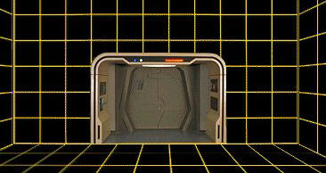
Star Trek’s Holodeck
Working Name: PPC
Descriptive Name: Parabolic Point Compression
Date Conceived: June 2002
Circumstances, or Problem
Right off the bat, I love Star Trek: The Next Generation. If you’re a Patrick Stewart fan then you’re already cool. Like everyone else, I loved the holodeck. The concept didn’t seem to be that far removed from reality. I thought it wasn’t unreasonable to have a holo-emitter in whatever space I needed it. I wanted to design something on my laptop, then hit a button and have the space above the laptop filled with a 3D model of the object.
I pictured a sphere with a smooth surface that I could manipulate with my hands. Being able to see a machine moving in space, zooming in and out to become intimately familiar with how something worked would be endlessly useful. The possible applications are endless.
 Most immediately, I wanted to use such a holographic device as a substitute for sand tables while in the field in the Marines. Sand tables are, well, sand or dirt (occasionally on a table) in piles that reflect real world elements like hills, valleys, rivers, etc. They are tangible terrain maps that help communicate ideas about the 3D battlespace to others. I imagined having pre-made the terrain we were in and some markers representing my troops. Then we could hash out right there what to do by moving the markers around and watching a prescribed scene play out, perhaps with a clock ticking in the background so that we could coordinate events realistically.
Very cool. Very useful. Possible? That remained to be seen.
Exploring the Solution
But I didn’t know how to do it. How do you put a pixel in space? Not the illusion of a pixel as some mirror tricks do (This principle has been used in arcade games and in museums for years), but genuinely right there in front of you so that a circle of people could see it from every side.
I thought of parabolics almost immediately, the principle in the holographic mirror trick. Light reflected by a parabolic surface all passed through the foci of the constituent arc. The problem with that, of course, is that the light doesn’t just stop there. It continues through and expands out again along the same path. I needed something at that same point in space to scatter the collected light.
My moment came while stationed at Camp LeJeune, NC. It was the middle of summer and we were at the new combat town doing training. I was walking toward a Hummvee when I saw the waves of heat propagating up and away from the hood, distorting the light headed to my eyes. I stood still there for a minute, sweating in all of my gear, and thought about what was happening. The air was largely staying in the same place.
What was happening was that heat was being transferred into the air just above the hood, causing those molecules to move faster, trying to get rid of that heat. They would pass the heat to those above them, cooling down, but causing the new carriers to speed up. Energy traveling through the air was causing locally high regions of air that were denser than the ambient air. That was how to do it.
Developing the Solution
I realized almost immediately that having the image spring from my laptop was either unlikely or a long way off. I assumed it would be monochrome and might only work in the dark. Limitations suck.
As the principles came together in my head and on paper, I was uncertain if my solution would work. I wanted a simple way to test it. I thought that if I could get a hold of a plastic, glass, or metal parabolic dish, I could point it at a dish of flour and tap the back of it with a hammer. If the foci created a disturbance, then it would probably work. Maybe. I looked all over for options and even bought several bowls and lids from second-hand stores to try out. Nothing quite did it. In retrospect, some speaker guts might have done the trick.
I proceeded as if the principle was valid as it was pointless to dwell until I had other options or could talk to someone about it. I focused on how the emitter of the pixel would work. That part was surprisingly simple with just a few speed bumps. The real challenge was finding a way to array them so that they could create the object. A TV or laptop screen only projects in one direction so the emitter array can be flat and two-dimensional. This was everywhere (within the limits of the display space).
At some point it occurred to me (probably while playing a first-person shooter) that I didn’t have to create every pixel in an object’s volume, just those pixels on the surface. Every object would essentially be one pixel thick. The pixels would be translucent so the user would see what was behind it.
Indeed, if I didn’t do it this way, the image would be ridiculously bright, like a tiny sun, photons scattering from every dot inside of the volume. That probably has some use, but it didn’t solve the challenge at hand. I worked up some options and thought I finally had a viable way for it all to work.
I tried to discuss it with an engineer buddy of mine. He suggested that if it could work, we’d already have them because it’s so simple. You’d think so. He made valid points about possibly being blinded by the light sources, how annoying the sound would be to the user or to pets, and he wanted to see the math proving it. At the time I had no answers. I still don’t have many. But I didn’t hear anything suggesting that it wouldn’t work, which meant that it might. And as it turns out, it does.
Concept
The Basic Principle
From my notes:
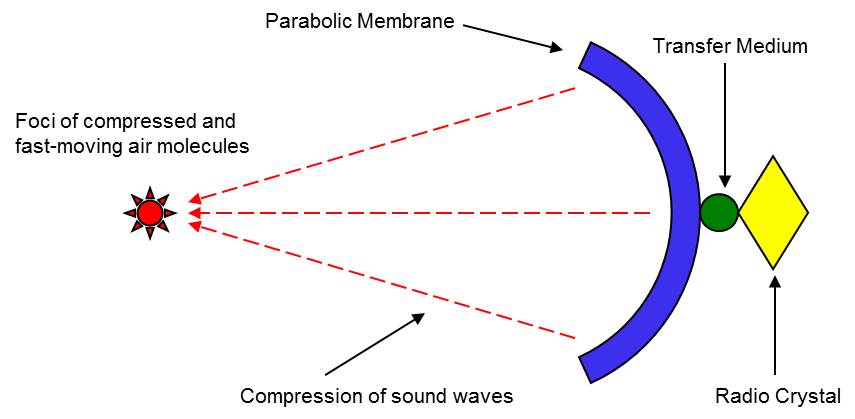
Using standard resonator technology (crystal diode or crystal resonator), transfer vibrations to a parabolic surface. The high-frequency sound waves compress at a foci where air molecules are locally far denser than ambient air. At this point air molecules will be moving rapidly and scatter the path of light, even as the wave continues through and out to dissipate. By using different sized/shaped crystal (changing amplitude, frequency, etc), the foci will behave differently. The “touch” principle of this can be demonstrated by pointing it down at a dish containing an even distribution of flour. The flour at the foci will be displaced by pressure and vibration. The distortion of light can be demonstrated by having a laser light source of the approximate diameter of the foci aligned perpendicularly to the line of the PPC. If it works, the point should appear brighter and a surface on the other side should receive more scattered light than would be expected. That is, the circle should be larger and less bright on a receiving medium opposite the light source. In the point-intercept 3D imaging system, this foci of compressed/active air scatters the focused light that would otherwise simply pass through this point. It also makes the point “feel” as if something is physically there. By changing the way the foci behaves (i.e., frequency, energy, size of foci, etc…), the user will “feel” the “texture” of the foci/pixel change.
Single Emitter
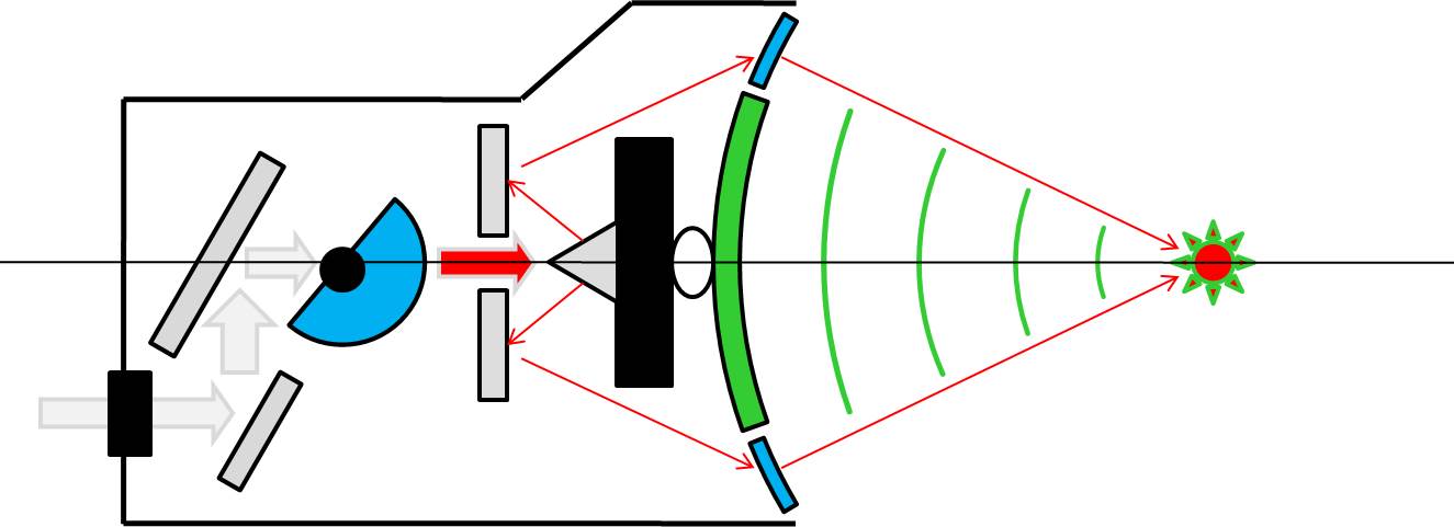
I made these diagrams in PowerPoint in winter of 2002. In the above diagram, gray materials are mirrors, blue are transparent. Colors can be created using a standard LED source (arrow path) and RGB filters (blue semi-circle) that move in front of it. The conical mirror deflects light to the transparent band that directs it to the foci. The black rectangle is the resonator which transfers its energy through a medium (oval) that won’t damage the vibrating surface. This was important back when I was still trying to run the sound and light through just one dish (which still should work).
As discussed, in theory a parabola isn’t necessary for the light source. A barely visible laser could be scattered at a point in the same way, making it more visible. The benefit of the laser method is interaction detection. The benefit of the parabola is reduced visibility of the light outside of the pixel. I suppose people are also less likely to be blinded by the parabola.
Developed
In the summer of 2008 (I discovered it in Jan 2009) the University of Tokyo demoed this same principle, calling it Touchable Holography (Which I concede is a much better name than PPC, describing what it does rather than how it works. After all, who gives a crap how it works?).
I was impressed that it worked, given that I continued to harbor doubts about whether enough light would be knocked off line and by a great enough degree to make a single point visible. This concern was verified by the fade-in/fade-out effect seen in the videos at the top and bottom of the figures. But who cares? It worked! I wasn’t an imbecile!
Sometime before I discovered this (not exactly sure of the when), I was learning about superwaves, a wave principle that creates enormous freak waves in the ocean that are almost impossible to detect until they rise up astoundingly high and sink a ship. I thought this would be a useful principle in PPC. I created an entry in my notes for Superwave Point Compression (SWPC), intended to accomplish the same thing as PPC, but using additive wave principles to get smoother virtual structures. I didn’t know enough math, physics, etc to know how or if this would work, so I waited to include a start date for the concept until I had a viable method for making it work. I haven’t yet so that’s still open turf.
Application 1: Lego Dreamworld
Lego Dreamworld is an open-format creation system that lets the user “make”3D shapes with their own hands. This requires one of two additional components:
• an infrared laser in the center of each emitter and a receiver placed perfectly opposite the emitter or
• two low-res cameras that associate their view of the 3D object with what exists in the program.
In either case, the user’s actions can be tracked the model adjusted in real time. A person could grab a giant ball of clay out of which they could sculpt a bust. They could design a toy train layout on their laptop and then create it in 3D, interacting with it at different scales and directly placing trees where they thought they should be and visiting the people in the town. The point of Dreamworld is to be limitless creative fun.
Application 2: InGame
The purpose of InGame is to place the user inside of a gaming experience. Utilizing a flat screen television, existing console systems to manage the input/output of the PPC projector, bicycle seat and oval foot plate device specified in other designs. Arrayed linearly on three sides of television, create an immersive game experience that covers a significant portion of player vision.
The player’s location and movement is determined by the foot plate device, a substitute for the body-movement thumbstick. Objects can appear to come toward a player that is moving and even brush by their skin or clothing. An arrow or bullet can come out of the screen and strike the user tangibly. A ball coming out of the screen can be swatted back to a character in the game. With a sufficient projector and console, large objects or even characters can be generated and interacted with, acting as game components, teachers (Mickey Mantel saying, “This is how you swing, kid.”) A pet can be generated that climbs out of the television and interacts with the user on the floor.
A user can begin to deeply understand a technology by zooming in (within the bounds of the projector) on and/or seeing inside of a particular aspect of an engine, molecule, organism, planetary system, or anything else that someone has created be it in a CAD program or elsewhere. A user can lean into a car engine to upgrade it, and test drive it in the associated racing game.
Application 3: Active Field Virtual Armor System (AFVAS)
Utilizing a portable tactical computer (cell phone size) and a very high frequency PPC array, create a disk/plane of air denser than ambient air at an angle to alter the path of an incoming bullet. It is expected that this will be similar behavior to a fired round entering a body of water, but it is difficult to predict with any certainty without experimentation. A grid of such virtual planes would surround the body and would activate as necessary or be turned on manually. It could also have standard angles for the planes and, when simply switched on, all fields would be at this setting.
I originally considered calling this AAFVAS, adding the word Adaptive and a slash (Active/Adaptive). It would utilize a smaller version of the Boomerang shot-detection system (http://bbn.com/boomerang) to create fields in a plane best suited to deflect specific incoming rounds. The obvious problem is that rifle bullets travel faster than sound and PPC works on sound. There simply wouldn’t be sufficient time to detect the shot, calculate the path, and then generate the field in time to deflect the round. The obvious solution is to keep it on constantly.
There are some technical challenges with this that I’ve had fun figuring out.
Application 4: Bug Barrier
I hate flies. Arrayed in a doorway, a human could walk right through a PPC “screen”, feeling like they were walking through a permeable skin, but flies and other insects would be stopped cold. I would amuse myself imagining them bouncing off in confusion.
As far as I know, none of these applications, even the most basic one that we have in common, is currently being explored. But I’m sure they’ll do something interesting with it. They’ve only had it for five years.
-CG